Piezoelectric actuators have demonstrated continuous operation in harsh conditions for more than 108 cycles. However, because of the many different applications, reliability will depend on many different figures. There is no readily available reliability model.
This figure would depend, among others, on:
- Temperature, cooling
- Humidity, contaminants
- Mechanical loading, preload, vibrations
- Operating spectrum
- Electrical field
Download Lifetime Test of Multilayer Actuators (PDF)
Precautions when designing a piezoelectric application
When designing a piezoelectric application, the following precautions should be taken in order to maximize the reliability:
- Make sure that the actuator does not heat up above the recommended temperature. Depending on the conditions, soft ceramics can heat up significantly when operated continuously at high frequency.
- Avoid exposing an actuator to high humidity levels. Humidity and contaminants can lead to electro-migration and eventually provoke a breakdown in the electrical insulation.
- Make sure that the ceramic always operates in compression. Piezo has a very limited tolerance to tensile stress. It is generally recommended to maintain a preload of around 20% of the blocking force in all conditions. In particular, high acceleration must be taken into account.
Please note
Every time the piezo drive voltage changes, the piezo element changes its dimensions (if not blocked). Due to the inertia of the piezo mass (plus additional mass), a rapid change will generate a force (pushing or pulling) acting on the piezoelectric actuator itself.
Tensile forces must be compensated for by a mechanical pre-load (inside the actuator or external) in order to prevent damage to the ceramics. Pre-load should be around 20% of the blocking force, with a springs stiffness around 1/10 or less compared to the piezo stiffness.
In sinusoidal operation with frequency f and amplitude ∆L/2, peak forces can be expressed in the formula:
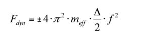
Where:
Fdyn = peak dynamic force (N)
meff = effective mass (kg) = (1/3)m piezo + m attached to the piezo
∆L = peak to peak displacement (meter)
f = frequency (Hz)
- Make sure that the driving signal is smooth. Voltage spikes can generate large accelerations.
- Load the actuator evenly. Uneven loading can rapidly lead to cracks in the ceramic material.
- Handle the parts carefully before mounting. Even if no damage is visible, small cracks can be initiated by shocks and further expand during cyclic loading.
- Reduce the electrical field to improve reliability.
- Avoid continuous operation under negative voltage, especially at high emperatures.